
Blog
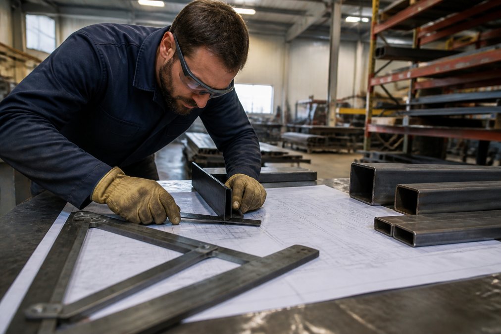
Table of Contents
Last Updated: September 19, 2026
Precision design is the practice of resolving every dimension, connection, and tolerance in a structure before a single piece of steel is cut, and it is the single biggest lever against costly mistakes in structural integrity work. At Antonio's Metal Works, we've spent over two decades fabricating structural steel, and the pattern is consistent: the errors that hurt most are born in detailing, not in the field.
A missed dimension on a shop drawing doesn't stay on the drawing. It becomes a wrong cut, a rejected shipment, a crew standing idle, and a change order. Detailing errors ripple through procurement, fabrication, and erection in sequence, and each stage adds cost that the previous stage could have prevented.
Watch Out The most expensive mistake we see is treating shop drawings as a formality. When a detailer copies an architect's dimensions without checking them against the structural drawings, the error gets baked into every fabricated piece before anyone catches it.
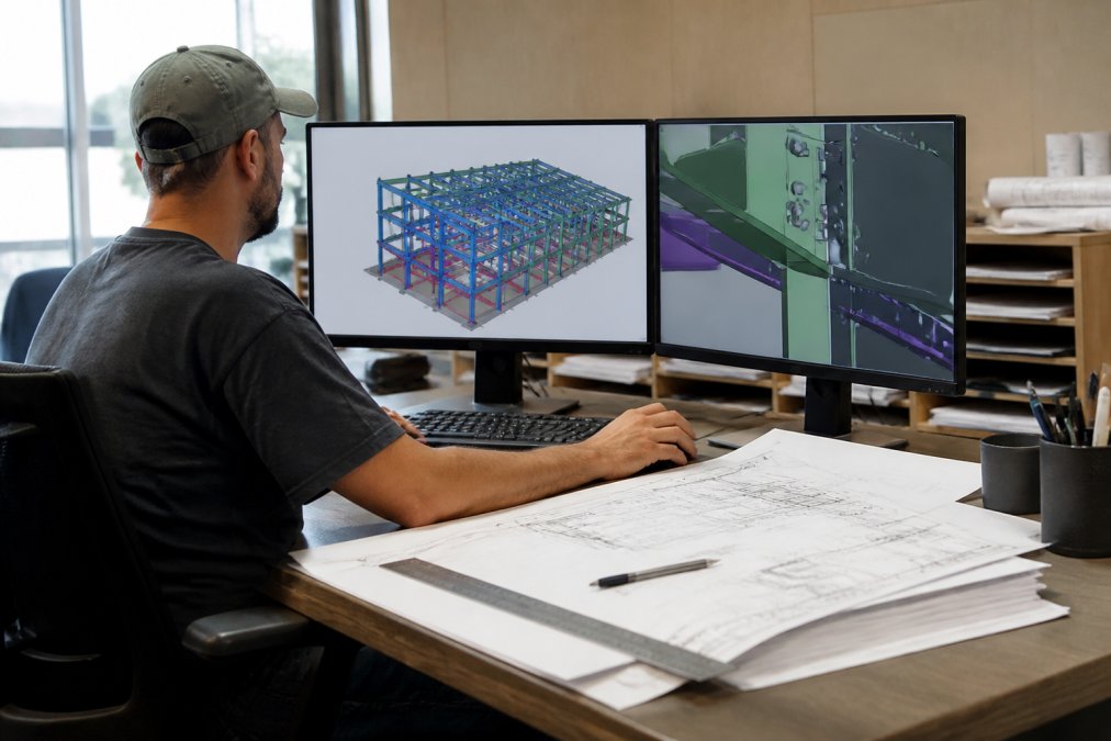
Good detailing starts with a full model, not a partial one. A detailer who builds the complete steel frame in 3D, including connections and embeds, catches conflicts before they reach the shop floor.
The best practices that prevent rework are unglamorous and consistent:
Clash detection is the process of running a 3D model against other trades to find physical conflicts before construction. For steel, this means checking beam penetrations, ductwork routing, and embed locations against the structural frame.
Dimensional accuracy in the model is only as good as the input. A common mistake is trusting a single source of dimensions. When the architectural and structural drawings disagree, the detailer must flag it rather than pick one.
The most common steel fabrication errors trace back to three sources: misread drawings, unverified field dimensions, and connection details that were never fully resolved. Each is catchable before fabrication with the right review step.
Catching them early means reviewing the drawing set against the model, confirming field measurements before cutting, and requiring the detailer and fabricator to sign off on connection details together.
Bolt hole misalignment is the most frequent connection failure in the field, and it almost always starts with a tolerance that was never specified. When hole sizes, edge distances, and erection clearances aren't called out, the fabricator guesses.
Connection details deserve their own review. A connection that works on paper can fail in erection if the sequence wasn't considered. The fix is simple: resolve every connection in the model and confirm it against the erection sequence before the shop starts cutting.
Structural integrity standards AISC publishes are the baseline for steel design and fabrication in this market, and design validation means confirming that every fabricated member meets them. The AISC standards and specifications define the tolerances, connection requirements, and fabrication practices that keep a structure safe.
The standards that matter most at the detailing desk are not the ones people cite in marketing copy.
Table 1
| Link | Owner | Artifact That Proves It |
|---|---|---|
| Design | Engineer of record | Sealed structural drawings and design calculations |
| Detailing | Steel detailer | Shop drawings and erection drawings checked against the design |
| Fabrication | Fabricator's QC | Mill certs, weld procedure specifications, and dimensional inspection records |
| Erection | Field superintendent | Plumbness, bolt-up, and final connection inspection reports |
Watch Out AISC 303 assigns responsibility for dimensions in a specific way: the fabricator is responsible for the fit-up of connections, but the engineer of record owns the design loads and the geometry that drives them. A detailer who silently 'fixes' a dimension to make a connection work has taken on liability that does not belong to them. Flag it in writing instead.
Two validation practices separate shops that catch problems from shops that eat them. First, every shop drawing should carry a revision block and a checked-by initial, so a reviewer can trace who approved which version. Second, any deviation from the structural drawings, even a hole shifted a quarter inch, should be documented as a request for information rather than absorbed quietly. The paper trail is what protects the project when a question surfaces during inspection.
Pro Tip Ask your detailer to produce a nesting plan alongside the shop drawings. Seeing how parts fit on stock lengths before ordering is one of the fastest ways to cut scrap without changing the design.
Now the part competitors skip. Every piece of rework is wasted steel, wasted energy, and wasted transport, and rework is a far bigger material loss than nesting scrap. A wrong cut member is not just one bad piece. It is the mill energy already spent producing it, the fuel already spent shipping it, the shop labor already spent fabricating it, and the new member that has to be produced, shipped, and fabricated to replace it. That is roughly double the embodied impact of getting it right the first time.
Interdisciplinary communication is where most precision design efforts succeed or fail, and it's the angle most guides skip. Steel doesn't exist in isolation. It interfaces with concrete, mechanical, electrical, and architectural work, and every interface is a place where dimensions can drift.
A workable protocol is straightforward:
Table 2
| Stage | Who Reviews | What Gets Confirmed |
|---|---|---|
| Design | Engineer and architect | Grid lines, loads, embed locations |
| Detailing | Detailer and fabricator | Connection details, tolerances, cut list |
| Pre-fabrication | All trades | Clash resolution, erection sequence |
| Pre-erection | Field and shop | Field dimensions, anchor bolt locations |
Key Takeaway The strongest QA process combines automated clash detection with a signed checklist. Software finds conflicts; a named detailer owns the decision to release the drawing.
Sustainability ties into this directly. Every piece of rework is wasted steel, wasted energy, and wasted transport. Preventing errors in detailing is one of the least glamorous sustainability measures in construction, and one of the most effective.
Detailing translates an engineer's structural design into fabrication-ready drawings that show every connection, bolt hole, weld, and member size. While design establishes load calculations and member sizing, detailing specifies exactly how each piece is cut, drilled, and assembled. Errors at the detailing stage, such as wrong bolt hole spacing or missed stiffeners, often surface during erection when corrections are most expensive. Precision design and detailing at this stage protects the structural integrity standards the engineer intended.
Bolt hole misalignment, missing stiffeners, incorrect weld symbols, and tolerance conflicts between trades top the list. Many of these trace back to shop drawings that were never cross-checked against architectural and MEP drawings. Clash detection during 3D modeling catches most conflicts before fabrication begins. A documented QA checklist that verifies connection details, member lengths, and hole patterns before release to the shop floor prevents the majority of field fixes.
Detailing errors compound. A misaligned bolt hole can force field welding, which requires re-inspection and may delay the erection sequence by days. Material waste from incorrect cut lengths adds procurement cost, and project rework consumes labor already committed elsewhere. Investing in clash detection, dimensional accuracy checks, and interdisciplinary coordination during detailing costs a fraction of what field corrections cost once steel is on site.
Shop drawings are the fabrication team's only instruction set. If a connection detail is drawn wrong, the piece is fabricated wrong, and structural safety depends on that connection performing as designed. Accurate shop drawings reflect load calculations, AISC requirements, and assembly requirements in one document. A single omitted dimension can produce a member that fits nowhere on site, forcing redesign under schedule pressure.
The American Institute of Steel Construction (AISC) publishes the primary standards, including the Code of Standard Practice and the Steel Construction Manual. These cover tolerances, connection design, fabrication drawings, and erection requirements. Detailing teams also reference AWS D1.1 for welding and ASTM specifications for material grades. Complying with AISC standards is not optional for structural safety; it is the baseline that inspectors, engineers, and fabricators all work from.
Call Us
(619) 241-2413E-mail Us
info@antoniosmetalworks.com


